
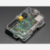
- 5V charge-pump voltage generator, so even though you are running 3.3V on a Pico board, it will generate a nice clean 5V as required by the transceiver.
- 3.5mm terminal block pre-soldered in to get quick access to the High and Low data lines as well as a ground pin.
- 120-ohm termination resistor on board, you can remove the termination easily by cutting the jumper marked Term on the top of the board.
- Pre-connected CS and INT pins on Pico GPIO #20 and #21. You can cut the bottom solder jumpers and use the breakout pads to connect to any two IO pins you like
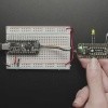
- Use the Pico Stacking Headers if you want to be able to plug into a breadboard or other accessory with sockets.
- Use the Pico Socket Headers if you want to plug directly in and have a nice solid connection that doesn’t have any poking-out-bits.
- Use the Short Socket Headers for a very slim but pluggable design; note that you’ll want to trim down the Pico’s headers or use the short plug headers on the Pico to have a skinny sandwich.
- Solder the PCB directly to the Pico headers – of course, this is very compact and inexpensive, but you won’t be able to remove the PiCowbell.
- Right angle JST SH connector for I2C / Stemma QT / Qwiic connection. Provides 3V, GND, IO4 (SDA), and IO5 (SCL)
- Reset button – Press to restart your program
- Every pad on the ‘bell has a duplicate hole pad next to them for solder-jumpering
- The ground pads have white silkscreen rectangles to easily identify, plus one long ground strip near the reset button
- Gold-plated pads for easy soldering
Be the first to review “Adafruit PiCowbell CAN Bus for Pico – MCP2515 CAN Controller Clearance For Nice”
Related products
Sale

Computer Accessories & Periphera
Original price was: $14.99.$12.29Current price is: $12.29.
Sale
Computers & Accessories
SanDisk Professional G-DRIVE PROJECT High-Capacity Thunderbolt 3 Hard Drive, 8TB Lowest Pice
Original price was: $429.99.$99.00Current price is: $99.00.
Sale
Computer Accessories & Periphera
Tripp Lite by Eaton N204-S15-BL-UP Cat.6 UTP Patch Network Cable Cheap Pices Authentic
Original price was: $21.40.$16.91Current price is: $16.91.
Sale
Computers & Accessories
Original price was: $659.99.$99.00Current price is: $99.00.
Reviews
There are no reviews yet.